In the winter of 2014 my wife’s 1999 Honda Civic overheated at the end of her drive home from college (about a three hour trip). After finishing up finals, I drove back home and met her at her mom’s house where the car had been moved into the garage so i could look at it. I found a lot signs of how bad the overheat was – the lid of the radiator overflow tank had melted, the label on the oil filter had shrunk to half its size, the valve cover smelled of roasted oil. One of my friends came up from St. Louis for a few days and helped me replace a large number of components and fluids: new radiator, new cooling hoses, thermostat, overflow reservoir, oil change, multiple coolant flushes, and the battery (I think it just happened to die around this time).
After all our work was complete, we fired the car up and it ran fine. However, I figured this wasn’t the last of the trouble – there was no obvious problem I had found during any of our work, nothing that seemed to be the root cause. After returning to school my suspicions were confirmed; the car was low on coolant. From there began a multi-month journey of trying every possible diagnostic method I had available to determine where the leak was. In the meantime, I kept a bottle of coolant in the back of her car and would regularly fill it up (every 3-4 weeks I’d put about half an overflow tank’s worth of coolant in). After trying leak-test dye, radiator headspace exhaust testing, radiator cap pressure testing – nothing turned up any obvious results. Everything pointed to a small leak between the cooling jacket and a cylinder, but small enough that my radiator headspace test didn’t turn up anything.
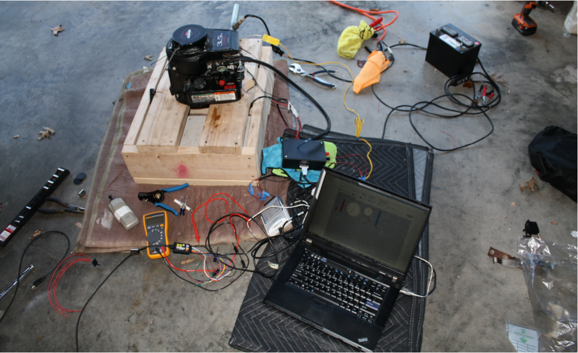
However, her car kept running, it just needed a bit of coolant every now and then. Fast-forward to December 2014. I take a job at Southwest Research Institute, we move to Michigan, and her car keeps on trucking. Finally, this summer I had to decide between selling the car or replacing the head gasket. I choose the later and below is a gallery providing an overview of the process. Before embarking on this project i had no experience in this sort of major automotive repair. I printed out roughly 40 pages of service manual information, watched numerous videos from Eric the Car Guy, and called numerous friends and family members with automotive experience.
The job in total took three weeks, a bit longer than I anticipated but twice I unexpectedly had to order parts (see the timing belt cover photo below). However, in the end, the car fired up and ran. I learned a lot in the process, and gained a decent amount of confidence in my auto tech abilities along the way.
Update (2017-07-15): The car ran without needing a drop of coolant for two years! While the car has been a good learning experience (since this post I’ve replaced roughly half the exhaust system, the power steering rack, and bled the brakes), I was definitely glad to finally sell it and upgrade to something a bit newer.
-

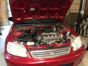
- Ready for teardown
-
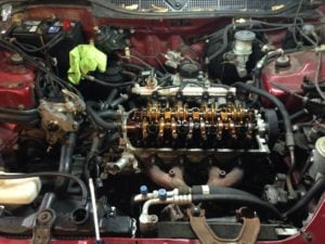
- Valve cover, distributor, fuel, and coolant connections removed.
-
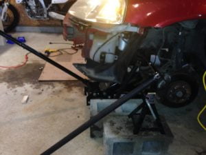
- Breaking the flywheel nut loose took an immense amount of force – this is a 4-foot breaker bar being supported by a jackstand on a cinder block. I thought I sheared something when it finally came loose.
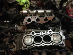
-
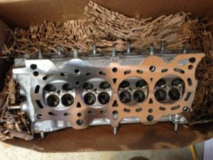
- Head removed from block and ready for teardown
-

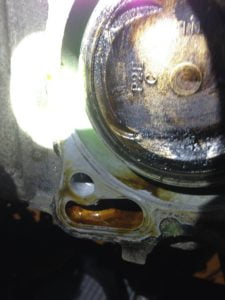
- Yahtzee! See that oil stain in the otherwise perfectly clean cooling jacket? That’s the leak, this is the site where I’ve been slowly loosing coolant.
-
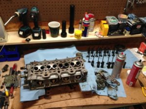
- Head fully disassembled in prep for a trip to the machine shop. The gray aerosol can is a gasket remover spray; it does its job, but I highly suggest buying the proper gloves (your standard latex shop gloves melt pretty much instantly).
-
- Head back from the machine shop! The shop confirmed that the head was warped (but the cam channel was straight); they resurfaced right up to the service manual max.
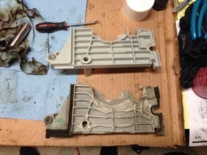
-
- Things got a little warm. This is the timing belt cover that sits between the head and the belt (there’s also an outer belt cover but it was not damaged).
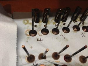
-
- While I had the head apart I lapped all of the valves – you can see the difference between the exhaust (closer) and intake (further) valve seats.

-
- Another comparison of pre/post valve lapping – the closer valves have been lapped.
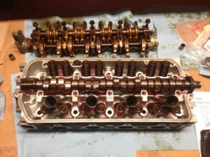
-
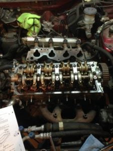
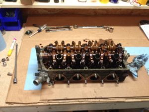
- Valvetrain almost fully reassembled. All of the valves are in, the cam is back in, just the rockers need to be reinstalled.
-
- Block surface prepped for a new head gasket.
-
- Head reinstalled!