As part of my “build a computer from scratch” project (overview blog post forthcoming) I need a keyboard. While building the USB stack from hardware up to software sounds like a fun project, I have quite a few other pieces to assemble and a PS/2 keyboard is much more expedient. So, I dropped by HSC Electronics Supply in Santa Clara and picked up the most old-school looking PS/2 keyboard the had, along with two 6-pin mini-DIN headers I could solder leads to.
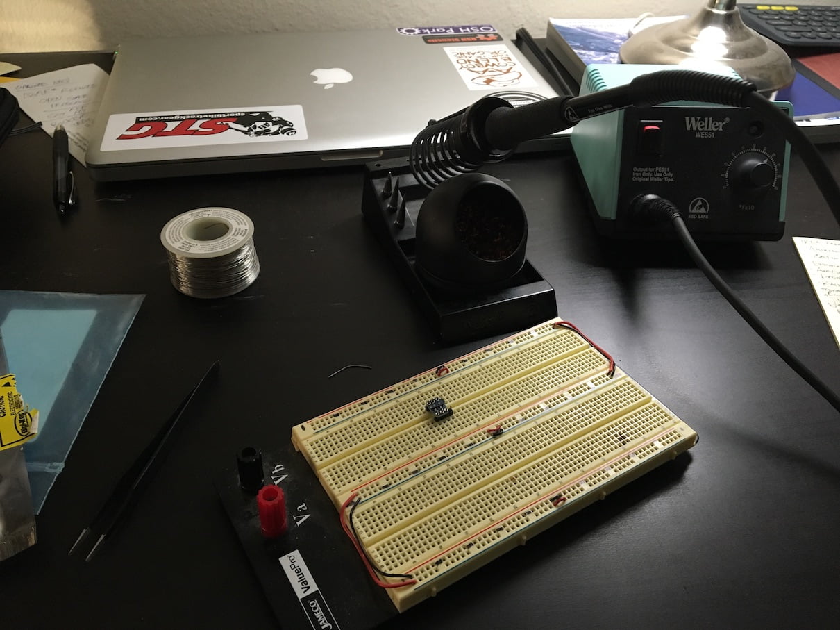
Having only read about the PS/2 specification I wanted to put theory to practice and see the output during a keypress event. So, I assembled my PS/2 breakout, broke out my power supply and breadboard, and wired everything together. I set up my logic analyzer to capture the clock and data channels and was pleased to find a PS/2 analyzer option – however, I did find that lower capture rates – I went all the way down to 1 MS/s – were required to make the analyzer function properly. My guess is the analyzer isn’t applying much, if any, filtering to the data stream and glitches are corrupting the decode state machine.
I set the trigger on the falling edge of the clock signal and powered the keyboard up, expecting to see a BAT message from the keyboard.
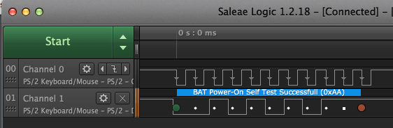
On power-up PS/2 keyboards enter the basic assurance test (BAT) state and, if successful, send 0xAA “BAT successful” to the host.
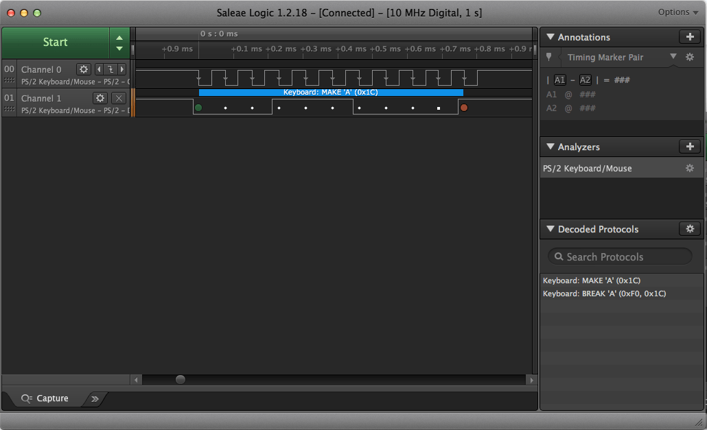
I restarted the capture and pressed “a”. In the capture below you can see the decoded messages in the lower-right panel – both the “make” and “break” messages were captured.
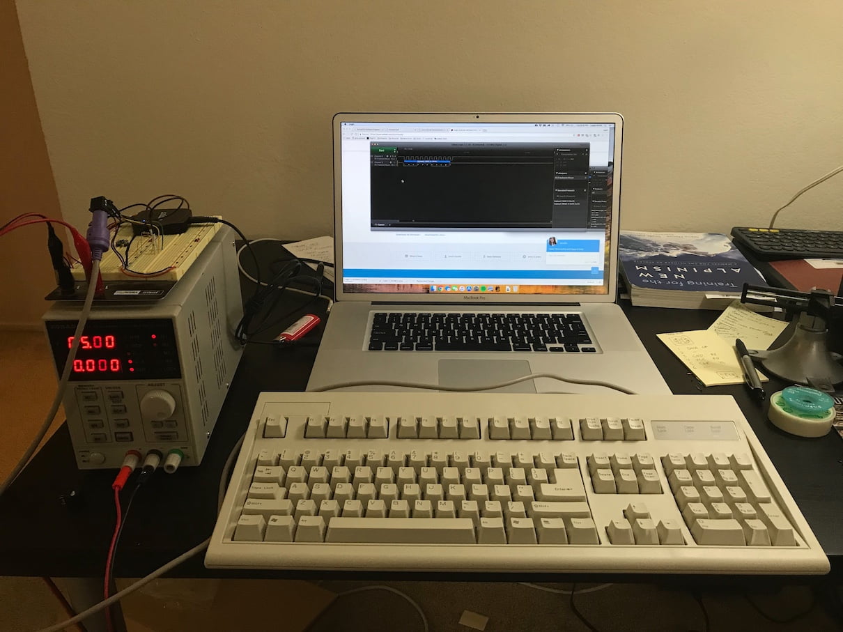
After assembling my PS/2 header I wired it up on my breadboard and pressed ‘a’ – success!
With the smoke test out of the way I moved onto my second target – level shifting the clock and data signals to 3.3V to be able to interface with my miniSpartan6+ dev board. I didn’t have any level shifter ICs on hand but I did have some SOT-23 FETs. So, I put two of my IRLML2060TRPbF FETs on a SOT-23 breakout board, added a few pull-up resistors, and turned on analog capture on the logic analyzer.
The result – a nice 3.3V output on the host side, perfect for my FPGA.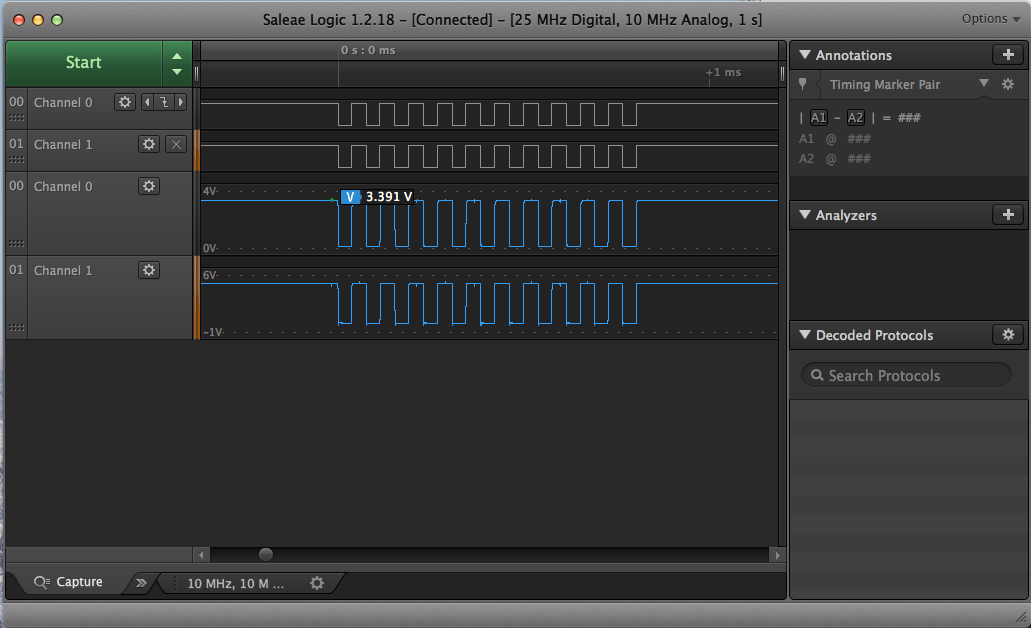
My next post will detail the PS/2 link layer and keyboard controller modules for the FPGA. The goal is to emulate the register interface standard for PS/2 keyboard controllers, on top of this I will build a simple module that will translate keycodes into ASCII characters and spit them out the serial port on the miniSpartan6+.