That is quite a title, but I’m hoping that it will help others find this post some day when they run in to the same problem that I’ve been running in to for a while – finding a single source of information that provides enough detail about how variable reluctance (VR) sensors work, how to interpret the waveforms generated by them and how to configure and understand the output of the hardware associated with them (specifically the MAX9924).
How VR Sensors Work
Disclaimer: I am not an electrical engineer. Don’t judge me.
In a sentence: VR sensors generate a voltage proportional to the speed of the moving object and the magnetic flux in front of the VR sensor pole. A cutaway shot of one will make that make more sense.

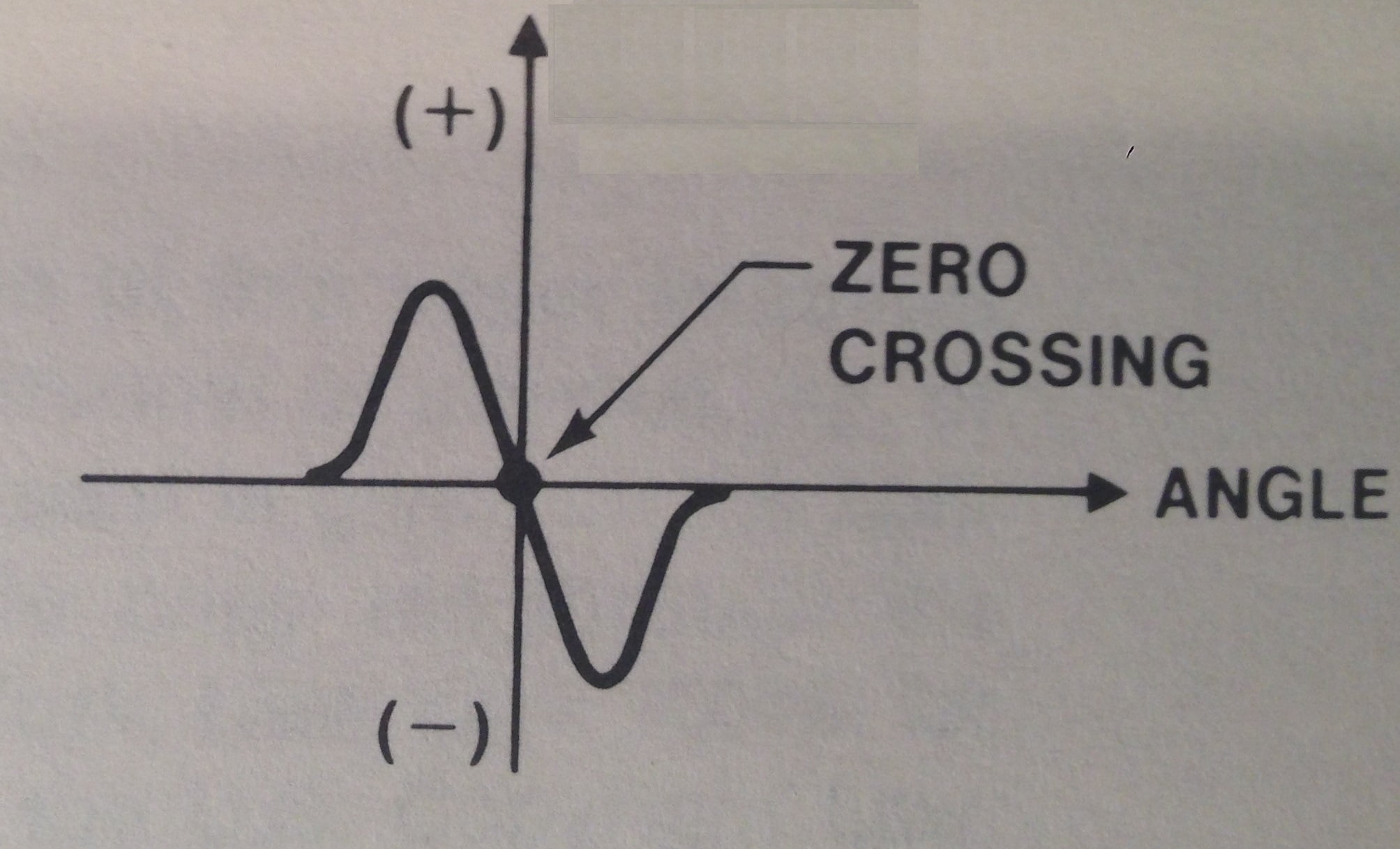
The voltage output is proportional to the speed of the moving object (in the automotive world, a toothed trigger wheel) so the output can range from millivolts to nearly a hundred volts depending on coil configuration and RPM. The output shape is essentially a sine wave – the magnetic flux varies from a minimum when the tooth is farthest away (largest air gap) to maximum when the tooth is centered with the pole piece (smallest air gap). Here’s the theorhetical output of a VR sensor.
And here’s a sample of me waving a screwdriver in front of a VR sensor I have.
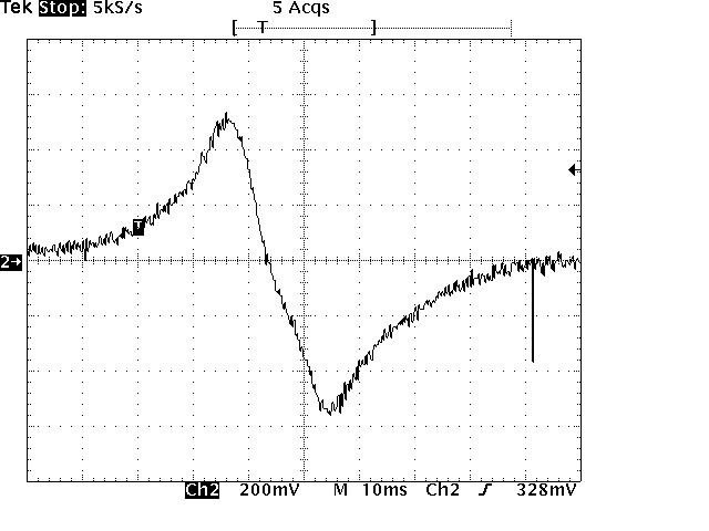
Pretty simliar, eh? The key point here is that the slope increases as the “tooth” gets closer to the center of the pole, then swings through zero in to the negative voltage region and then returns to zero – this is the pattern you will see for all VR sensors (when properly connected, if you see the opposite then you’ve probably switched the positive and negative lines of the sensor).
How to Interpret a VR Signal
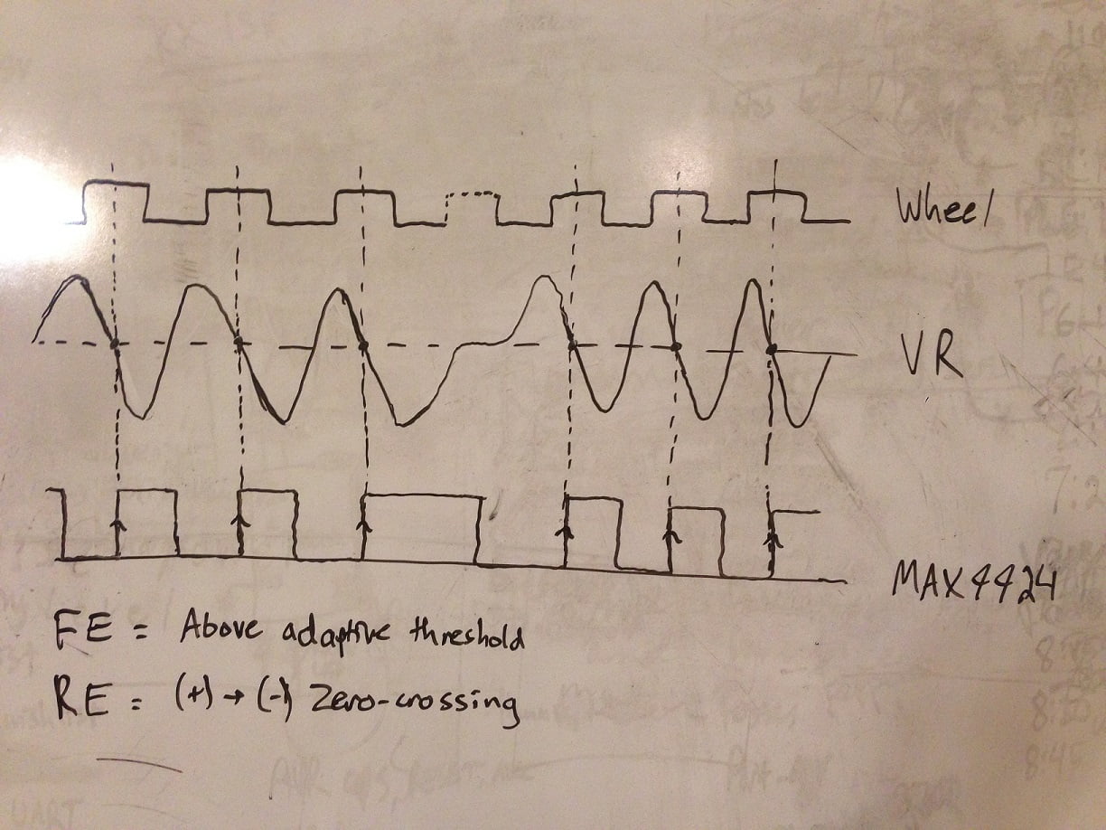
The most important part of the VR sensor output signal is the zero-crossing from positive to negative voltage. This point is almost exactly (there’s a slight electrical delay resulting from the combination of the sensor and the processing circuitry we’ll talk about in a bit), and for our purposes is, the center of the tooth lining up with the center of the pole piece. Here’s a nifty graph I drew on my whiteboard to illustrate this point.
VR Sensor Signal Conditioning
So now you’ve got this sine wave coming from your VR sensor and you want to use it as an input to your microcontroller or ECU. How do you go about doing that? You go out and buy a chip that does everything for you like the LM1815 or the MAX9924. I’ve used both, they both do the job. ThumperFI has the MAX9924 because after researching the topic on the forums, people seem to like the MAX9924 more than the LM1815 – it seems that it’s better at detecting small signals among other benefits.
I’m not going to go in to the specifics of how the MAX9924 does what it does – not only because I only have a marginally decent knowledge of how it works but because you don’t really care (well, I guess I can’t know that but I’m going to assume that you want to know THAT it works, and how to configure it, rather than the technical details. If you want to know that, go read the datasheet).
The MAX9924 datasheet agrees with what I’ve told you above:
The zero-crossing signal provides true timing information
for engine-control applications. The zero-voltage
level in the VR sensor signal corresponds to the center
of the gear-tooth and is the most reliable marker for
position/angle-sensing applications.
Basically, the MAX9924 generates a square wave that your microcontroller/ECU can read. The falling edge corresponds to the VR signal crossing the adaptive peak threshold (i.e. the voltage goes above a certain voltage) and the rising edge corresponds to the zero-crossing point. Pay attention to that, the rising edge of the MAX9924 signal is the edge that you need to time off of. If you go back and look at the signal diagram I drew above you’ll see that the rising edge lines up with the zero-crossing which lines up with the center of the tooth. Here’s a scope capture of me swinging that screwdriver in front of the VR sensor again only how I have the output of the MAX9924 on ThumperFI overlaid on the VR signal.
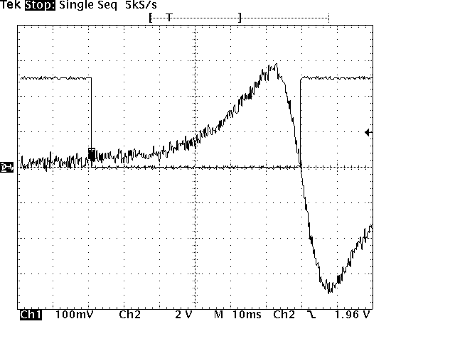
You can better understand the adaptive threshold with this picture – notice how the trigger lines up with the signal when it’s slightly offset from zero? That’s the trigger threshold happening – it’s this magic that makes the MAX9924 so great at what it does.
Conclusions
That’s basically what I wanted to outline in this post – how a VR sensor works, what kind of signal it generates and how to process that signal to generate something useful. Any questions you have can be directed below to the comments section.