Since 2010 the Yamaha YZ450F has had electronic fuel injection (EFI). To support the new electrical loads of the bike – more powerful ECU, fuel pump, fuel injector, additional sensors – Yamaha beefed up the stator and added a capacitor to help with start-up transients (this is a battery-less system and still starts first kick!). However, after all of these loads are taken into account, the stator has roughly 50W of additional power available for accessory loads. The two largest loads on a street legal bike are the headlight and radiator fan (with the horn pulling up a close third). Even with a high-efficiency LED headlight the load can be as high as 20W, and a radiator fan (like this one) can draw 24-30W. To overcome these limitations, I decided to design a control unit to:
- Provide HI/LO functionality for the headlight
- Control radiator fan speed
- Automatically dim the headlight when the radiator fan is on
This post details the design process I took to arrive at a functional control unit.
MOSFET Evaluation
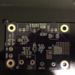
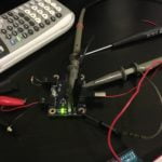
While still working on specifications for the final design, I decided to take a detour on a small side project to more closely evaluate MOSFETs and associated driver circuitry. At this point, I hadn’t designed a board to drive any sort of real load, so I was curious about the behavior of the associated electronics. I designed a PCB to evaluate the MOSFET I was considering for the final design (IRFR3806), as well as a MOSFET driver (IRS44273L). I included a BNC connection for the input signal (as I expected to use a function generator to drive it), as well as removable Molex connectors for the supply voltage and drive output, and test points to check the voltages at the input, gate, and drain. I also used an 0805 resistor between the driver output and the MOFSET gate labeled “SLEW” on the silk – I didn’t end up playing with this part, but the idea was I would be able to control how quickly the driver charged the gate by swapping out this resistor for different values.
-

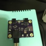
- Prepping the board for reflow
-
- Paste spread and stencil removed
-
- Board fully assembled and ready for testing
-
- I don’t have a function generator at home, so I grabbed an Arduino I had on the desk and had it spit out a square wave.
-
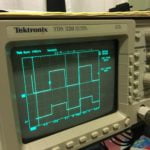
- Everything working as expected. Trusty TDS320 working hard.
I happened to be reading the FET chapter in The Art of Electronics while working on this project, so I grabbed a scope shot of the gate voltage:
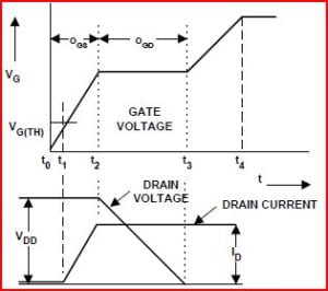
Always cool to see theory reduced to practice.
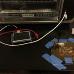
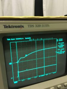
The next day I brought my board and fan into work to take advantage of the higher-end equipment I had available. As part of the design I included a current shunt resistor – the Fluke seen in the picture is measuring the voltage across it. With this setup I was able to easily perform a number of tests:
- Carrier frequency evaluation – because the fan makes a large amount of noise, this frequency could be much lower than the one used for the headlight (I don’t have any pictures of testing that with this board).
- Duty-cycle to current table

I’ve been spoiled by the MSO4034 at work, makes my TDS320 look a little sad.
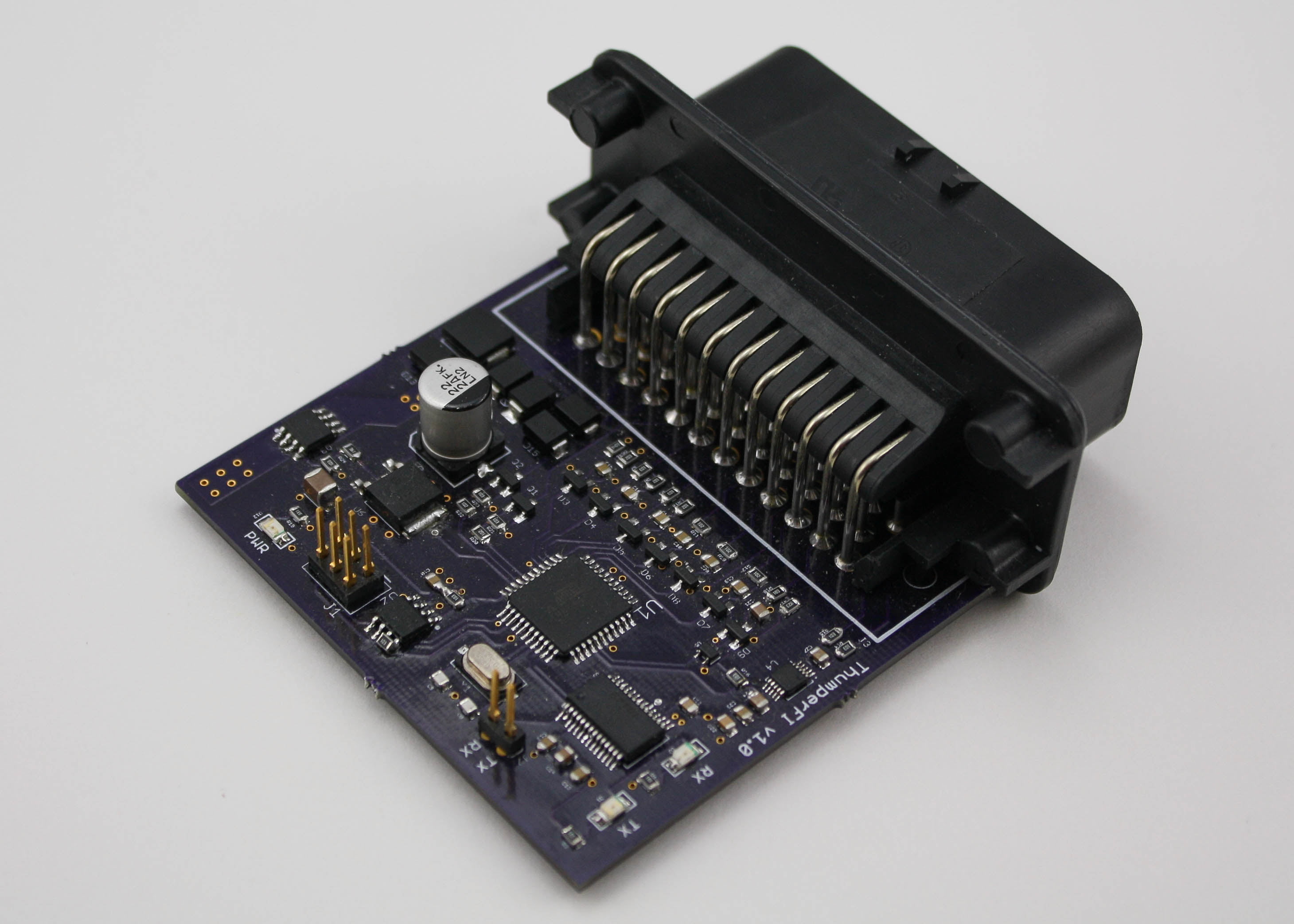
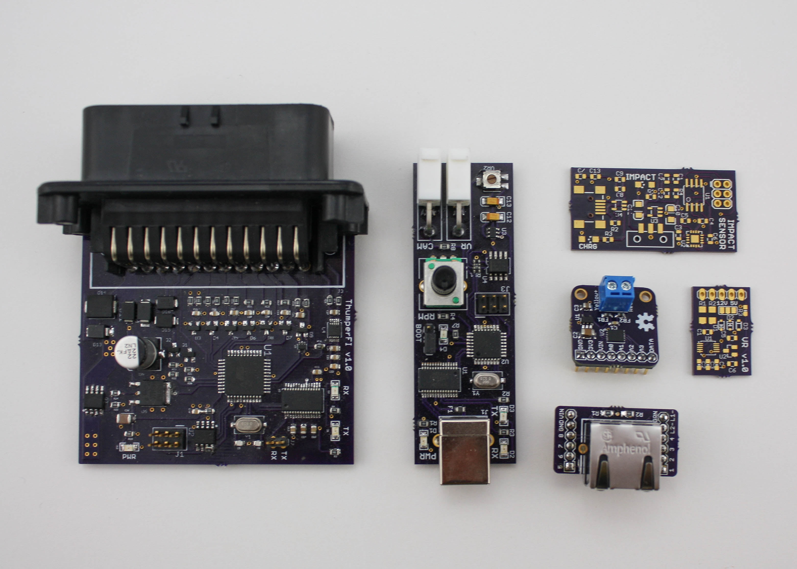
Control Module Development
Let’s start with the good stuff, the assembled board:

Assembled! This was a fun one, first board I’ve made with 0402 components.
I ended up switching to a smaller, “lower” power capacity MOSFET for the final design (BSC340N08NS3G). I targeted a rather small enclosure from Digi-Key, in part because I didn’t want some honking enclosure in the headstock and in part because I like a good challenge (and because OSH Park charges $5/in^2, I’m always seeing just how small I can make something). The design is simple, there are two identical output channels and three identical input channels. I used an ATMega168PB, a low-power version of the classic ATMega168A.
Coming soon:
- Schematics
- Description of firmware
- Photos of it working